John Heisz's homemade table saw
|
John writes about the rationale behind his table saw project:
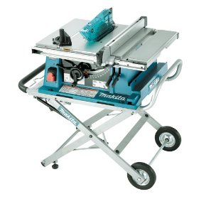
The saw was on a folding stand and is (was) the table top type but a hefty version.
(see pic). It was 3 years old (I paid ~$500.00 on special at Busy Bee) and I just got
sick of its shortcomings - mainly the fence. I thought at first that I would sell
it and buy a better one but the better ones cost substantially more than I would
have gotten for the Makita....
My reasons for building the saw are economy - a saw with these rip and crosscut
capacities is not cheap and it has a relatively compact footprint: my shop has
limited space. Oh, the challenge and I enjoy it (you understand).
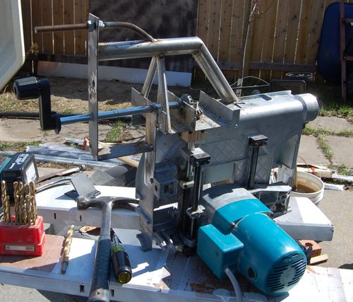
John's saw is based on the motor from his old Makita saw:
The motor assembly is from a Makita contractor saw that I modified to work here.
The motor assembly is the only part of the Makita saw that was any good - powerful, quiet,
high RPM and an electric brake. Lining it up accurately was tricky, but the end result
is very rigid and easy to access for adjustment (if needed).
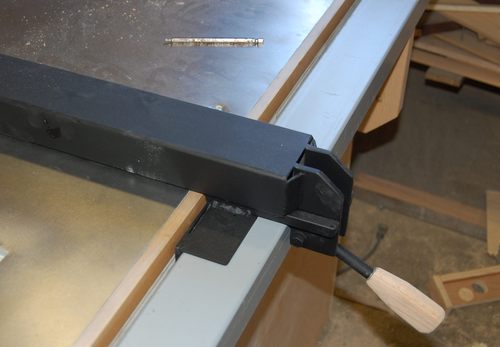
John's added an extended lever to more easily and precisely set the
angle on the saw. The extension is made of welded tubular steel.
The angle setting is fast and easy - I opted for this style to simplify it and
to make quick angle settings (without endlessly cranking a hand wheel). Increasing the
radius gives me more precision on the scale as well. It needed to be rock solid, the steel
welded on looks a bit overboard but it is all needed.
That rinky dink little plastic crank was from the original saw.
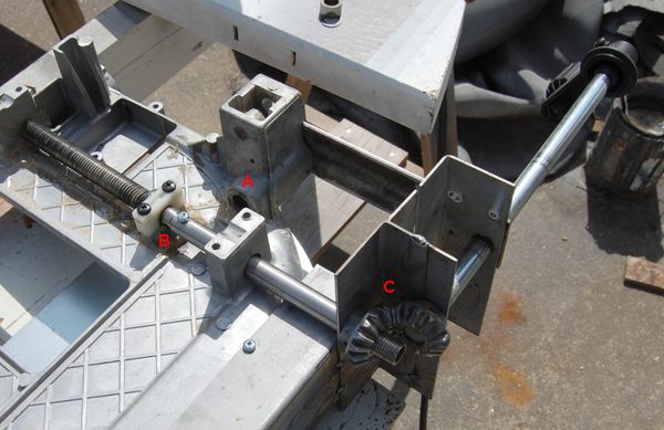
Moving the depth adjustment crank downwards necessitated further modifications.
"The bevel gears are part of the motor lift and I had to extend the vertical shaft by 6" -
one of the main problems with the old saw was that when set to 45° the up-down crank was
nearly touching the fence rail, making it next to impossible to turn. By extending the
shaft, I effectively moved the crank axle down, away from the fence rail."
Originally, the shaft and adjustment crank were mounted at 'A', coupled with a depth
adjustment screw with bevel gears at 'B'. After modifying, an extension couples where
the bevel gears used to be, and the bevel gears are moved to 'C'.
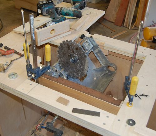
The depth of cut at 90* with a 10" blade is 3 1/8"
I only lose ~1/4" in maximum depth of cut to the original contractor saw as the
mounting point is higher than the bottom of the top. In the pics, that is an 8 1/4"
blade (Freud makes a really good 24 tooth ripping blade - $24.00 at Rona) that I
normally use. A 7 1/4" will still rip a 2 x 4 no problem but I have several 10"
blades in any case.
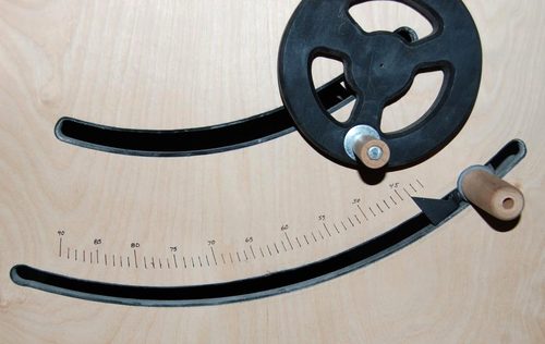
I made the new 7" hand wheel from Baltic birch ply (2 layers of 1/2")
and the handle is sapele - much nicer.
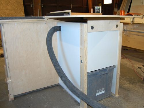
The bin catches nearly everything (it's one of the best ideas I've ever had) and
the 2.5 inch hose connects to my dust collector to pull the fine dust that gets
airborne during a lot of cutting - it makes a huge difference.
The hose is just connected to that
enclosure and captures the fine dust. It doesn't go through to the exhaust.
Most of the time this hose is not connected - it's only when I'm doing a lot of
cutting or cutting something obnoxious like mahogany (I hate the taste of that)
or MDF.
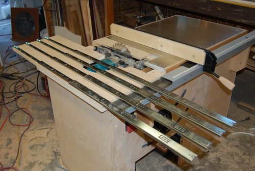
The table rides on four 28" full extension drawer slides (see attached pic). It has very
smooth action and no lateral play. Also seen in the pic, the original top was 2
layers of 1/2" particle board with a stainless steel surface but it was not flat
enough (hence the new concrete top).
My main objective for the sliding table was to minimize lateral play to give an
accurate cut and to make the whole assembly easy to disassemble for cleaning and
lubrication. With the slides flat and with the other support mechanisms in place
(aluminum stiffening rails between the slides) , there is very little (negligible?)
vertical play at the blade, where the maximum support is. The largest panel I would
crosscut is ~24" and most times a lot less than that. It works much better than I
expected and using 4 of the slides really helps to eliminate play.
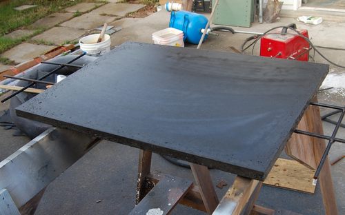
To cast the concrete top flat I stacked some sheets of 3/4" birch plywood on my assembly
table and topped that with a piece of 5/8" melamine. I spent some time checking this
form for flatness. I cut strips of plywood to 1" to form the edge. The concrete is a
fiber reinforced bag mix, 30mPa with some non-shrink grout added and black
pigment - my el-cheapo granite top: $10.00. It is extremely flat and of very consistent
thickness. I need to let it cure for another week or so before I fill it and seal it.
It is exactly 24" x 32" x 1" and used one 30kg bag of concrete mix.
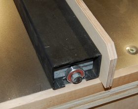
The fence has drilled and tapped holes in each side of the front angle for set screws
but I haven't had to put them in - I did a really good job of squaring the fence to
the guide rail. The guide rail itself can also be adjusted
The fence has strips of "slippery tape" on the front angle part and with the bearing
in the end, it glides across smoothly and effortlessly. The bearing at the end is the
only part of the fence that touches the top.

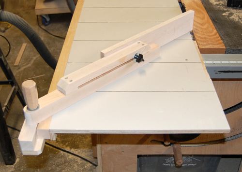
I finally got around to building the proper crosscut fence for my sliding table.
It is surprisingly solid and quick to adjust and remove - it uses one of 2
pivot pin locations on the table for maximum 90 degree crosscut of 24" and max
45 degree cut at 11". I feel this is more than adequate for my needs.
 More details about this table saw
http://www.ibuildit.ca/table-saw-1.html
by John Heisz
Pages: 1 , 2 , 3 , 4 , 5 , 6
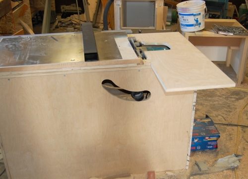
For many woodworkers, the table saw is the one tool that gets the most use - I know that is true for me. Having a good table saw makes all of the cutting tasks a little easier, especially if it has advanced features. Unfortunately, good table saws with advanced features usually have a high price tag attached. Being frugal (cheap) and always up for a challenge, I went to work to build my own table saw.
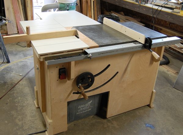
Here's how it turned out:

Some key features are a homemade Biesemeyer style fence that locks to the front rail, a max ripping capacity of 34", a sliding table with max crosscut capacity of 24", 3" max depth of cut (with a 10" blade) and an integrated outfeed table with dust collection.
The base is a simple plywood box with 4 sides. Made from 3/4" maple plywood, it has 2" x 2" solid wood cleats to join the corners with screws. On top of this box is a plywood and oak frame that supports the motor assembly, sliding table and the top.
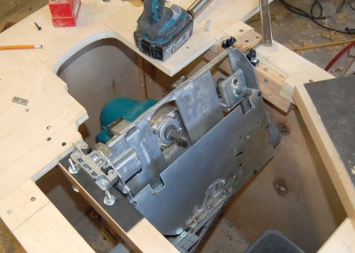
Shown here is the frame mentioned above and the motor assembly being mounted:

The motor is from a portable Makita table saw that I was using before building this. It was a reasonably good saw, with the best part being the motor, but it had a few glaring shortcomings. I've never regretted my decision to scrap it for this build.
I did have to heavily modify the motor assembly to better work in this saw though. Shown here is how I extended the blade elevator mechanism to increase the arc of blade tilt control.

A problem with the Makita, when the blade was tipped to 45 degrees, the elevator crank was nearly touching the underside of the top, making it extremely inconvenient to raise or lower the blade. By extending the blade elevator crank axle down an extra 6", I solved this problem.
Much steel was added to the original motor assembly to accommodate this longer arc. Holding the assembly rigidly during cuts is critical and I took no chances on the modifications being too weak:

Mounting the motor was a bit tricky. I had to fabricate a new trunnion part for the rear mount from solid oak:

I left the front mount adjustable from side to side, for alignment.
Elegantly functional and beautiful besides.
ReplyDelete