http://www.ibuildit.ca/Workshop%20Projects/router-table-1.html
Plans are now available for a lift based on this design, see them here
Pages:
1 ,
2 ,
3 ,
4 ,
5 ,
6 ,
7 ,
8
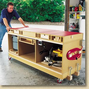
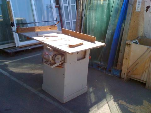
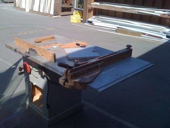
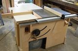
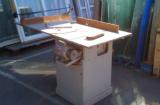
My
router table
has seen a lot of use lately, as I've been using it on many of my
recent projects. While it is certainly well made and very capable, I
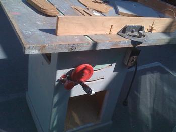
thought I could improve a few things. First off, having the raise /
lower and locking controls inside the cabinet is a bit annoying. I have
to open the front access door (sawdust invariably spills out) and reach
inside to make adjustments. I started thinking of ways to put these
controls up front and in doing so, eliminate the access door. My first
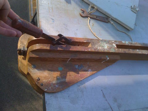
idea was to blank out the opening and make an extension for the crank
gear and locking knobs. Threaded rod, some coupling nuts and a new hand
wheel would do the trick and in a couple hours the work would be done.
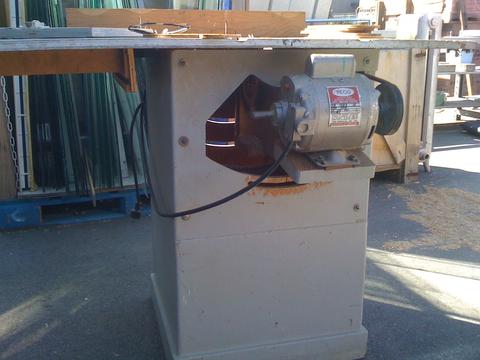
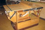
Then I got to thinking about the other "problems" there are with the
table: how heavy it was (that's good and bad: good for staying put, bad
for moving it around), how the top didn't overhang the base on the
front, making it very difficult to clamp on jigs and feather boards. The
storage situation was less than ideal as well, as I have run out of
space for router bits - I would have to convert one of the side drawers
into a bit tray.
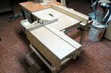
So, while I was thinking of these possible upgrades an idea for a
new kind of lift mechanism percolated up from my subconscious. I found
this idea so compelling, I used it as the excuse I needed to start an
all new router table design.
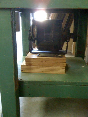
The lift uses an inclined plane to raise and lower the router motor.
This is a simple concept and should be quite reliable in operation.
Building it should be fairly easy, with no complicated parts. Tolerances
need to be tight, but that would be the case for any machine of this
type.
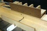
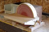
It starts with the inclined plane and here I've laid out the shape on 1/2" thick Baltic birch plywood:

The dimensions were determined when I modeled it in SketchUp.
What I was looking for was a total vertical lift of ~4" and to get it as
close as possible to a 2:1 ratio for the horizontal travel of the
inclined plane. My thinking was that 2:1 would be about as steep as it
should be, to avoid putting excessive lateral force on the components
while it is pushing the motor up. In the end, I wound up with slightly
less than 4" lift for a horizontal run of ~7".
To make the action smooth and low friction, sealed bearings are used to ride on the incline, one above and one below.
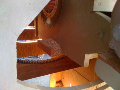
Cutting the angle:

This is about the only thing I use the laser on my mitre saw for: it's very handy for lining up angles that I haven't measured.
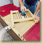
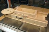
With the angle cut, I drill holes in the corners:


This is to allow me to use the (old) router table to cut out the centre.
Yes, using a router table to build a router table. These cuts could
also be done on the table saw, or with a jigsaw or with hand tools (if
you're into that).
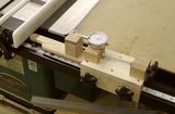
The important part is that the top and bottom edges of the incline be smooth and parallel:

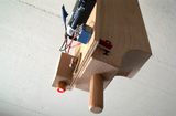
A strip of UHMW plastic is fastened to the bottom:


This rides in a track. It is free to move forward and back and the UHMW plastic acts as a bearing.
The incline is used to lay out the location of the sealed bearings:


The bearings should be as close to the incline as possible but having a little play here is not a big deal.
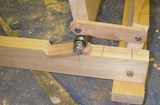
I use 3/8" threaded rod to bolt the bearings in place. The
spacing is such that the incline slides easily between the pieces of
plywood:


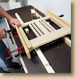
The clamp that will hold the router body is made from 1/2"
plywood and solid maple. It is sized for a body diameter of 3.5", which
is fairly standard.

To guide the router up and down, another layer of plywood is added to the carriage.
It has strips of UHMW plastic on its edges, which act as bearings.
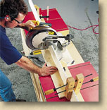
The motor clamp is notched to allow access to the nut on the bearing shaft:


The tracks that the carriage rides in are cut from a piece of
solid maple. Here I've cut the track long enough to get two, one for
each side.

 Place a piece of scrap wood under the opposite end of the 1-by-3 to hold it up off of the floor. Attach the wood pieces together at the crossover using four wood screws.
 Put a 1/4-inch gouging bit into your router and make a groove on each side of the 1-by-3.


